| Back | Next | Table of contents |
Function
Set ( Reset ) | Inverse | Rising edge pulse | Falling edge pulse
Interlock ( Clear ) | Jump ( Label ) | Call ( Label , Return ) | End | Diagnostic |
|
|
| h Set ( Reset ) |
|
| MITSUBISHI's PLC |
OMRON's PLC |
 |
 |
|
|
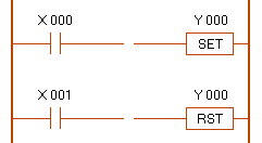
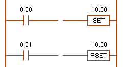
* When the Set coil turned ON,
the coil keep ON,
until the Reset coil turned ON. |
X 000
0.00 |
X 001
0.01 |
Y 000
10.00 |
| OFF |
OFF |
OFF |
| ON |
OFF |
ON |
| OFF |
OFF |
ON |
| OFF |
ON |
OFF |
| ON |
ON |
OFF |
|
|
|
|
|
|
| h Inverse |
|
| MITSUBISHI's PLC |
OMRON's PLC |
 |
 |
|
|
| * The ( ON - OFF ) condition of the coil is reverse. |
X 002
0.02 |
Y 001
10.01 |
| ON |
OFF |
| OFF |
ON |
|
|
|
|
|
| h Rising edge pulse |
|
| MITSUBISHI's PLC |
OMRON's PLC |
 |
 |
|
|
* When the Input's state is turned ON,
the coil turned ON for only one scanning.
* PLS = Pulse
* DIFU = Differential Up |
X 003
0.03 |
Y 002
10.02 |
|
| OFF |
OFF |
|
| ON |
ON |
For one scanning |
| ON |
OFF |
|
|
|
|
|
|
| h Falling edge pulse |
|
| MITSUBISHI's PLC |
OMRON's PLC |
 |
 |
|
|
* When the Input's state is turned OFF,
the coil turned ON for only one scanning.
* PLF = Pulse Falling
* DIFD = Differential Down |
X 003
0.03 |
Y 002
10.02 |
|
| ON |
OFF |
|
| OFF |
ON |
For one scanning |
| OFF |
OFF |
|
|
|
|
|
|
| h Interlock ( Clear ) |
|
| MITSUBISHI's PLC |
OMRON's PLC |
 |
 |
|
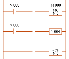
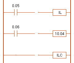
* When the Inter-lock coil is OFF,
the middle coil is always OFF.
* MC = Master Control
* MCR = Master Control Reset
* N 0 = Nested number |
X 005
0.05 |
X 006
0.06 |
Y 004
10.04 |
| ON |
ON |
ON |
| OFF |
ON |
OFF |
|
|
|
|
|
|
| h Jump ( Label ) |
|
| MITSUBISHI's PLC |
OMRON's PLC |
 |
 |
|
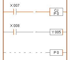
* MITSUBISHI mode
When the Jump coil is OFF,
the middle coil can turn ON-OFF.
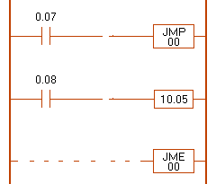
* OMRON mode
When the Jump coil is ON,
the middle coil can turn ON-OFF.
* CJ = Conditional Jump
* P = Pointer
* JME = Jump End |
| X 007 |
X 008 |
Y 005 |
| ON |
ON |
OFF |
| ON |
OFF |
OFF |
| OFF |
ON |
ON |
| OFF |
OFF |
OFF |
|
| 0.07 |
0.08 |
10.05 |
| OFF |
ON |
OFF |
| OFF |
OFF |
OFF |
| ON |
ON |
ON |
| ON |
OFF |
OFF |
|
|
|
|
|
|
| h Call ( Label , Return ) |
|
| MITSUBISHI's PLC |
OMRON's PLC |
 |
 |
|
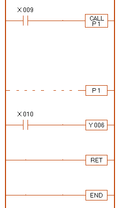
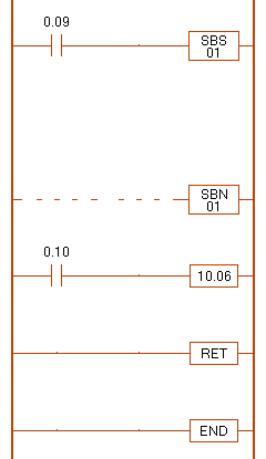
* When the Call coil is ON,
the middle coil can turn ON-OFF.
* P = Pointer
* SBS = Subroutine call
* SBN = Subroutine Entry
* In case of the MITSUBISHI-FX
SRET = Subroutine Return |
X 009
0.09 |
X 010
0.10 |
Y 006
10.06 |
| OFF |
OFF |
OFF |
| OFF |
ON |
OFF |
| ON |
OFF |
OFF |
| ON |
ON |
ON |
| OFF |
ON |
ON |
| OFF |
OFF |
ON |
|
|
|
|
|
|
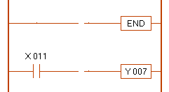
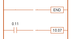
| h End |
|
| MITSUBISHI's PLC |
OMRON's PLC |
 |
 |
|
* Set the End coil at the end of the program.
* The circuit of the bottom side from the End coil
is ignored by the simulator. |
X 011
0.11 |
Y 007
10.07 |
| ON |
OFF |
|
|
|
|
|
|
| h Diagnostic |
|
 |
|

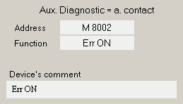
These address are dummy for the explanation. |
 |
|
|
1. Set the diagnostic device on the [ Device Registration ] mode.
2. Set the contact of the diagnostic device on the [ Program ] mode.
3. Click on the [ Function ] box of [ Edit ] screen.
4. See the comment bar of software. |
|
|
|
| Folder - 02 |
|
|
|


